
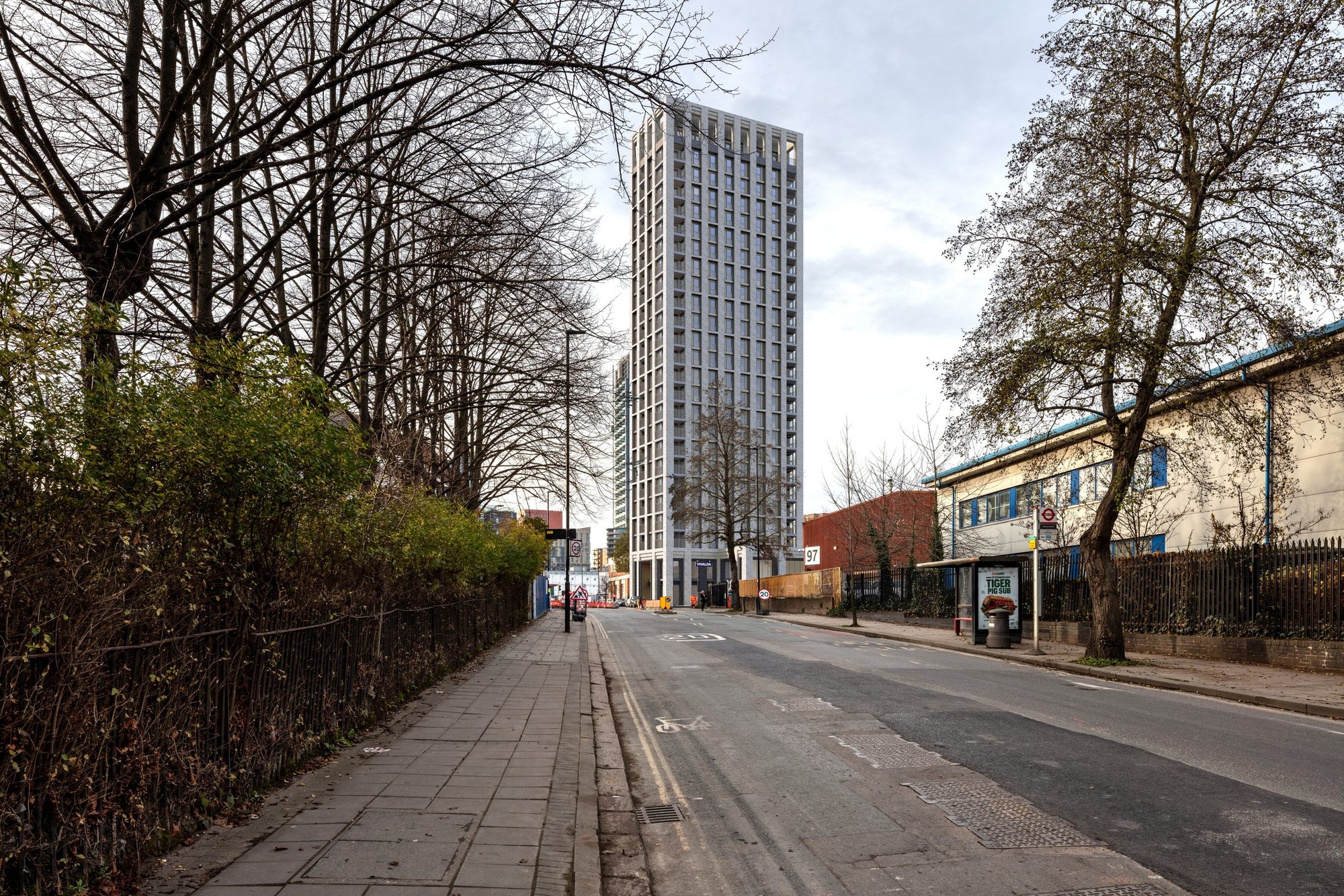
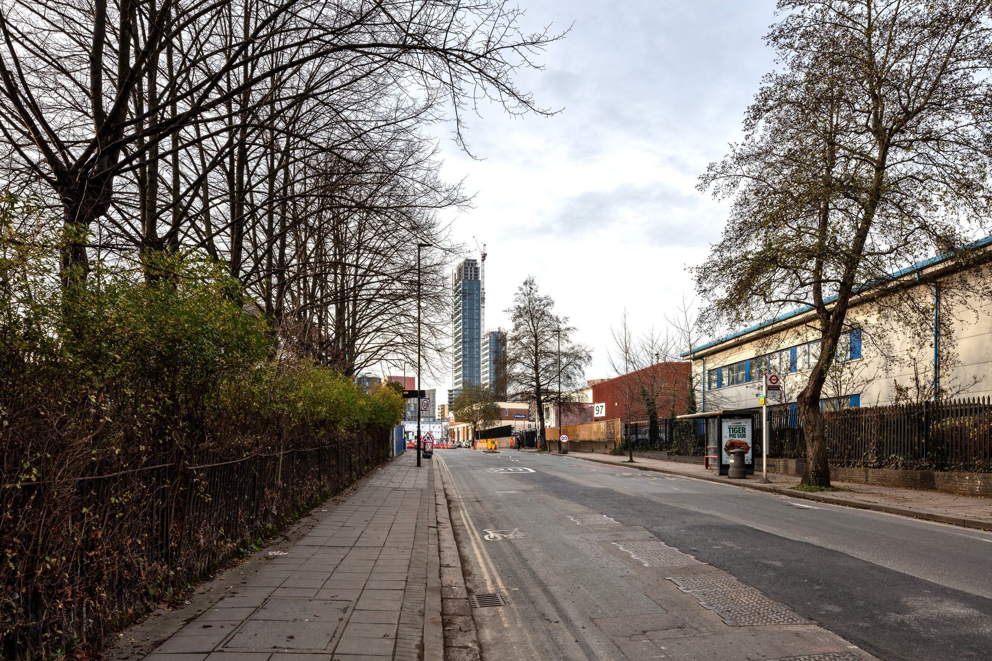
 PhotographProposed
Methodology
How a verified view is made, what in it is measured, and what is a judgement. Every objectively measurable property of a view can be traced back to surveyed control and recorded camera data, so it can be audited by a third party.
The eight stages
The same sequence on every viewEach stage produces recorded data or imagery that can be checked independently, from surveyed control through to the printed image.
- PhotographyRAW capture on a full frame camera, levelled, with the lens centred over the surveyed ground mark at 1.6 m, within the 1.5 to 1.65 m eye height range in TGN 06/19.
- SurveyAn independent surveyor records the camera position, height, bearing and reference points in the photograph, using RTK GNSS and total station, in OSGB36 with heights to Ordnance Datum.
- 3D modelBuilt from the architect's drawings and models, checked against plans, sections and elevations, and positioned in OSGB36 using a recorded false origin.
- Camera matchingA virtual camera is set from the surveyed height, bearing and field of view, then aligned until the surveyed points overlay the photograph.
- Independent checkA second qualified team member verifies the match. An overlay print is kept as a permanent record of match accuracy.
- Lighting and renderSun position set from the recorded date, time and location, aligned to true north. Materials from the architect's specification, rendered to the agreed AVR level.
- CompositionThe render is placed on the photograph with non-destructive masks where foreground buildings or trees interrupt the view. The recorded scene is not edited; lens correction and any stitching are stated in the method statement.
- Output and graticuleFixed print size, with horizon line, optical axis and field of view markers on every view so its geometry can be checked.
Surveyed control
School Road, view 3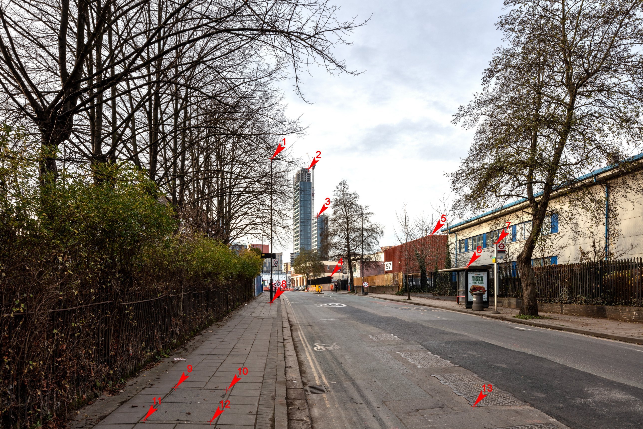
Survey accuracy
| Method | Plan | Height |
|---|---|---|
| RTK GPS / GNSS | ±10 to 15 mm | ±15 to 20 mm |
| Total station, reflectorless | ±5 mm | ±5 mm |
| Photogrammetry / DSM | ±1.5 m | ±1.5 m |
Tolerances accord with the RICS guidelines for the use of GPS in land surveying.
Why it matters
| Distance from camera | Apparent shift per 1 m camera error |
|---|---|
| 10 m | 5.70° |
| 100 m | 0.57° |
| 1,000 m | 0.057° |
| 10,000 m | 0.006° |
This is why near views are always survey-verified. Long-range views may be matched to 3D city models or LiDAR data, and the source is declared for every view.
Schedule of viewpoints
School Road, Appendix A.1, camera height 1.6 m| View | Lens | HFoV | Type | Date and time | Bearing | Easting | Northing | Height AOD (m) |
|---|---|---|---|---|---|---|---|---|
| VV01 | 24 mm | 73.7° | AVR 0 | 09/12/2021 14:09 | 47.4° | 520773.224 | 181894.159 | 33.729 |
| VV02 | 24 mm | 73.7° | AVR 3 | 09/12/2021 13:54 | 17.8° | 520970.253 | 181932.375 | 34.974 |
| VV03 | 24 mm | 73.7° | AVR 3 | 22/12/2021 10:57 | 184.5° | 521170.057 | 182238.936 | 30.421 |
| VV04 | 24 mm | 73.7° | AVR 0 | 22/12/2021 10:36 | 102.3° | 521038.928 | 182382.716 | 34.244 |
| VV05 | 24 mm | 73.7° | AVR 3 | 22/12/2021 10:49 | 94.5° | 520856.729 | 182177.829 | 37.943 |
| VV06 | 24 mm | 73.7° | AVR 0 | 09/12/2021 14:47 | 154.7° | 520758.101 | 182158.354 | 39.801 |
| VV07 | 24 mm | 73.7° | AVR 0 | 22/12/2021 10:25 | 229.6° | 520842.942 | 182552.249 | 36.037 |
| VV08 | 50 mm | 39.6° | AVR 0 | 10/12/2021 10:38 | 228.1° | 520769.915 | 182933.607 | 32.974 |
| VV09 | 24 mm | 73.7° | AVR 0 | 22/12/2021 11:02 | 296.2° | 521272.603 | 182347.555 | 29.733 |
| VV10 | 50 mm | 39.6° | AVR 0 | 10/12/2021 11:16 | 95.1° | 521685.479 | 182883.586 | 39.613 |
| VV11 | 50 mm | 39.6° | AVR 0 | 10/12/2021 12:00 | 317.6° | 522258.162 | 182238.790 | 30.062 |
| VV12 | 24 mm | 73.7° | AVR 3 | 22/12/2021 12:04 | 293.8° | 522045.115 | 181687.619 | 21.165 |
| VV13 | 50 mm | 39.6° | AVR 0 | 10/12/2021 13:42 | 265.2° | 521818.981 | 181287.051 | 13.733 |
| VV14 | 50 mm | 39.6° | AVR 0 | 09/12/2021 15:16 | 162.7° | 519920.898 | 181707.541 | 34.432 |
| VV15 | 50 mm | 39.6° | AVR 0 | 09/12/2021 16:14 | 221.1° | 519199.705 | 182299.323 | 46.275 |
| VV16 | 24 mm | 73.7° | AVR 0 | 10/12/2021 12:39 | 63.9° | 521295.843 | 182008.789 | 31.921 |
Camera: Canon EOS 5DS R with TS-E 24 mm f/3.5L II and EF 24-105 mm f/4L. Survey: Warner Land Surveyors, GNSS baseline with robotic total station, processed in N4ce. Season: winter, leaf-off.
The photograph is evidence
From camera to plate
- RAW fileCaptured with manual exposure, and kept
- ConversionTo a high bit depth TIFF, with no adjustment that affects scale, geometry or visibility
- Lens profileOnly the manufacturer's calibrated profile, checked against straight surveyed edges
- Safe areaThe distorted outer edges of the frame are left out of the camera match
What is kept for every view
- PhotographyRAW file and corrected background plate
- SurveySurveyor's data for the camera and reference points
- Camera matchThe match files and the archival overlay print
- Sign-offStatement signed by the operator and countersigned by the independent checker
Lenses and viewing
Lenses are chosen for what the assessment needs, not for effect. The horizontal field of view is recorded for every view and used as the main check. In a built-up setting a 50 mm lens is not always appropriate, as the London View Management Framework notes; a 24 mm lens lets the viewer read the urban context. Shift lenses are used vertically only, so tall buildings are framed without converging verticals.
Printed views should be held at arm's length, or at the distance implied by the print width and field of view.
| Lens | HFoV | Used for |
|---|---|---|
| 105 mm | 19.5° | Long-range relationships, distant detail |
| 50 mm | 39.6° | Standard lens, close to focused human attention |
| 35 mm | 54.4° | General purpose, moderate context |
| 24 mm | 73.7° | Urban settings, constrained spaces, tall buildings |
| 17 mm | 93.3° | Very constrained viewpoints, panoramic needs |
Guidance followed
- London
- London View Management Framework SPG, Appendix C
- Landscape Institute
- TGN 06/19, Visual Representation of Development Proposals
- GLVIA3
- Guidelines for Landscape and Visual Impact Assessment
- Modelling
- Autodesk 3ds Max
- Rendering
- Chaos Corona
- Compositing
- Adobe Photoshop
- Insurance
- Professional indemnity insurance held, certificate on request