Methodology
How an AVR is built.
Every Accurate Visual Representation we produce follows a rigorous five-stage workflow governed by LI TGN 06/19 (Type 4), GLVIA3 and LVMF Appendix C. The process is documented at every stage and produces an audit trail that can withstand independent scrutiny at planning inquiry.
01
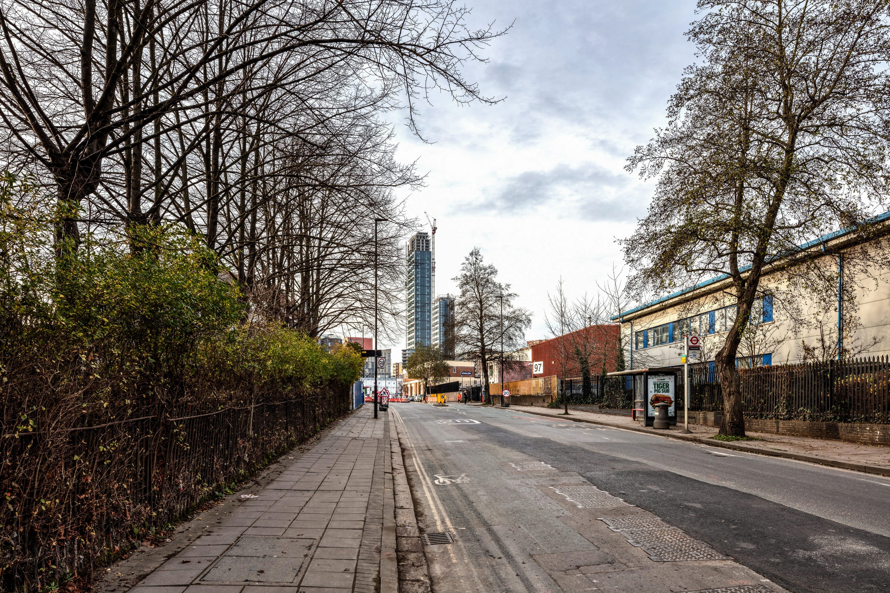
Site Photography
Full-frame Sony A7R IV (61MP) mounted at exactly 1.60m eye height on a calibrated panoramic levelling base with a nodal slide to eliminate parallax error. The camera is levelled in both axes; plumb bob marks the ground station directly beneath the lens. RAW capture with full EXIF metadata. Lens selection follows LI TGN 06/19, which identifies the 50mm prime (39.6° HFOV) as the benchmark for verifiability. Wider tilt-shift lenses are used only where the full proposed height cannot be captured at 50mm, and each choice is justified in the per-view data sheet.
02
Topographic Survey
An independent RICS-qualified surveyor records camera station coordinates using RTK GNSS (Geomax Zenith 60), achieving accuracy of ±10 to 15mm horizontal and ±15 to 20mm vertical under normal conditions. Camera height is recorded to Ordnance Datum Newlyn. A minimum of eight identifiable ground control points are surveyed, with the coordinate system established to OSGB36/OSTN15. Where higher accuracy is required, a Geomax Zoom 90 total station delivers ±5mm reflectorless EDM.
03
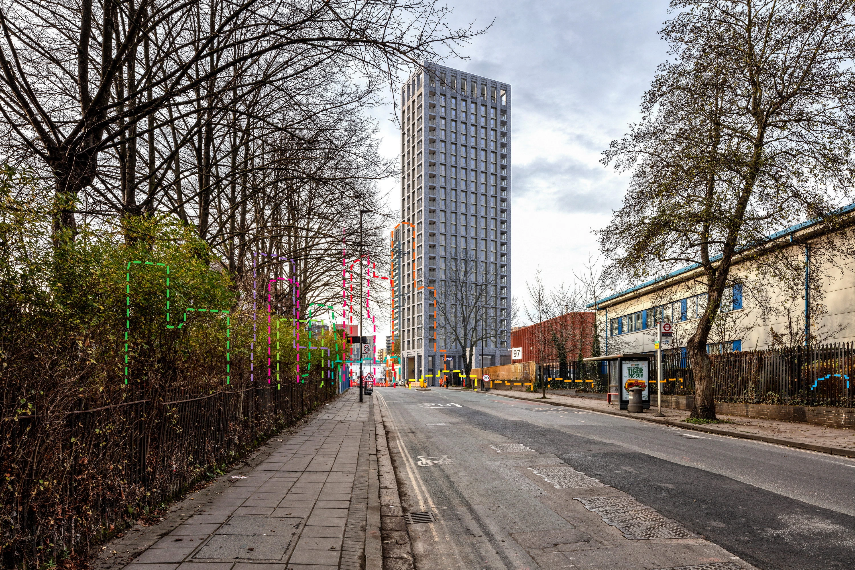
3D Model & Camera Match
The proposed development is modelled in 3ds Max from architect-issued CAD or BIM data and geo-referenced to OS coordinates. AOD levels are confirmed in writing with the project architect before rendering begins. The virtual camera is then aligned to the surveyed station: focal length, sensor dimensions and principal point are set to match the physical camera, and lens distortion is mathematically corrected. Surveyed reference point markers are placed at OSGB36 coordinates and iteratively refined until overlay is confirmed. The alignment overlay is retained as a permanent verification record.
04
Rendering & Compositing
The scene is rendered using Chaos Corona with a solar position calculated from precise astronomical algorithms applied to the exact date, time and geographic coordinates of the viewpoint, with True North alignment translated from OSGB36 Grid North. Foreground elements are masked non-destructively and all layers retained. The finished composite is reviewed by a second qualified team member before release. Material finishes and vegetation are approximated from specification documents: this element is rigorous interpretation, not independent verification, and we make this distinction clearly in every methodology statement.
05
Deliverables
Every commission includes: verified view images at each viewpoint (existing and proposed conditions); viewpoint location plans with 12-digit OS grid references; camera data schedule recording coordinates, bearing, lens, HFOV, date and time; survey data summary with accuracy statement; per-view technical data sheets; and a full LI TGN 06/19 Type 4 methodology statement, inquiry-ready. Wireline overlays and cumulative scheme views are provided where required by the competent authority or the planning consultant.
Note on verification
What "verified" actually means.
Verification applies to the documentation of inputs, not to a post-production audit of the final rendered image. The camera position, survey coordinates and building geometry are recorded with sufficient precision that they could be independently confirmed by a competent surveyor. In practice, no independent re-survey takes place: the methodology is auditable, not the output. What is verified is the data. What is represented is the image. These are related claims, and we make both honestly. LI TGN 06/19 §1.3 notes that visualisation effort must be proportionate to the scale, sensitivity and requirements of the competent authority.